Controlling ODrive from an Arduino via CAN
Overview
This page describes how to control an ODrive via CAN using an Arduino and the ODriveArduino library.
The library is compatible with the following setups:
Arduinos with built-in CAN interfaces that use the native Arduino framework (such as Arduino UNO R4 Minima, Arduino UNO R4 WiFi and others)
Teensys with built-in CAN interfaces that are compatibly with FlexCAN_T4 (Teensy 4.0, Teensy 4.1)
Arduino-compatible boards with MCP2515-based CAN shields
This library is primarily intended for runtime usage, such as changing states, sending setpoints and reading position/velocity feedback. While the CAN protocol allows for the modification of any configuration variable, this is often much easier to accomplish in the ODrive GUI or the odrivetool. More information about the underlying protocol can be found here.
Connecting the Arduino to the ODrive
First, connect your Arduino to the ODrive. Below you see an example setup. Your setup may look different depending on your hardware, please see the notes below.
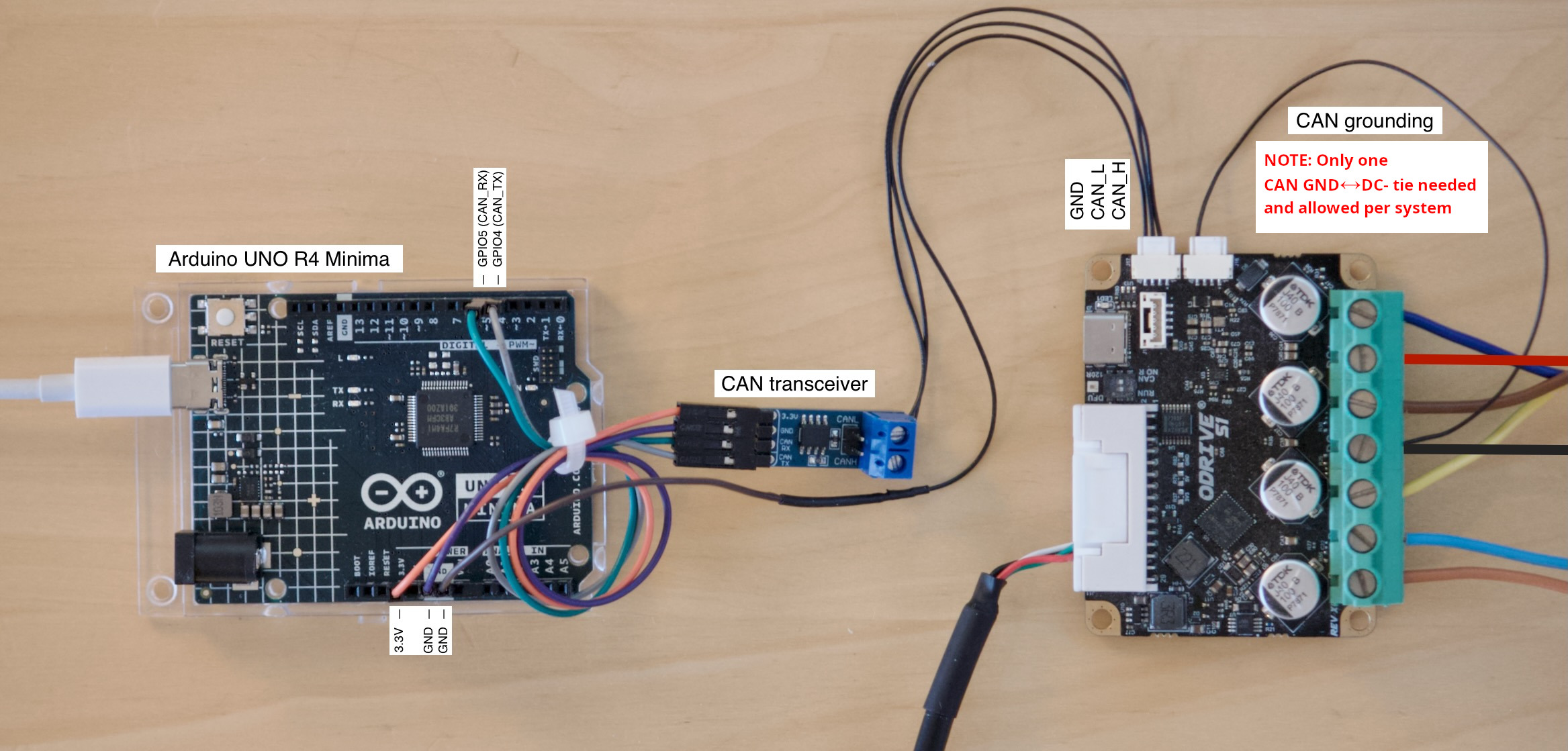
Arduino connected to ODrive S1 via CAN. Click to enlarge.
The Arduino UNO R4 Minima shown on this picture has a built-in CAN interface but no CAN transceiver. That means we need an external transceiver.
The CAN transceiver on this picture is a Waveshare SN65HVD230 CAN Board.
CAN bus ground must be connected to DC- at one single point in the system. On this picture, this is done with a single wire on the ODrive’s second CAN connector. See Hardware Setup for more details.
If you’re using multiple ODrives you can simply daisy-chain them together.
When using an ODrive Pro, it must be powered through DC+/- to be able to communicate via CAN.
Configuring the ODrive
Next, configure your ODrive according to your application. The easiest way to do this for the first time is via USB in the Web GUI.
Note
It is possible to set up a fresh ODrive purely via CAN, however this is currently not possible from the GUI and requires scripting instead. See Arbitrary Parameter Access for more info.
Connect your ODrive to your PC via a USB isolator, open the Web GUI and follow the Configuration wizard.
Most settings depend on your hardware so we won’t go into detail here. However there are a few settings specifically needed for this example:
Control Mode page: Select Filtered Position Control mode with a bandwidth of 100 rad/s.
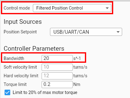 odrv0.axis0.controller.config.control_mode = ControlMode.POSITION_CONTROL odrv0.axis0.controller.config.input_mode = InputMode.POS_FILTER odrv0.axis0.controller.config.input_filter_bandwidth = 20
Interfaces page: Enable CAN, enable feedback messages and set the Node ID to 0 (or something unique for every ODrive if you have multiple).
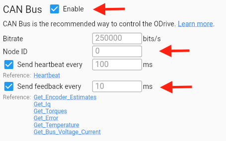
Optionally you can also enable the watchdog (also on the Interfaces page). This will make the ODrive stop when the CAN connection gets disrupted.

When you’re done configuring, go to the Dashboard to verify that you can send position setpoints from the GUI before proceeding with the next steps.
Warning
If you have already enabled CAN and come back to this step to change something, make sure to disable CAN first or disconnect/unpower the Arduino. Otherwise the Arduino sketch might interfer with the GUI.
Installing the ODriveArduino Library
Open your Arduino IDE.
Go to Sketch > Include Library > Manage Libraries.
In the Library Manager, type “ODriveArduino” into the search box.
Click on the entry for the ODriveArduino library, then click “Install”.
Example Sketch
Finally, upload the following example sketch to the Arduino. You can also find this under File > Examples > ODriveArduino. This example will put the ODrive into closed loop control and then move the motor back and forth in a sine wave pattern.
  1#include <Arduino.h>
  2#include "ODriveCAN.h"
  3
  4// Documentation for this example can be found here:
  5// https://docs.odriverobotics.com/v/latest/guides/arduino-can-guide.html
  6
  7
  8/* Configuration of example sketch -------------------------------------------*/
  9
 10// CAN bus baudrate. Make sure this matches for every device on the bus
 11#define CAN_BAUDRATE 250000
 12
 13// ODrive node_id for odrv0
 14#define ODRV0_NODE_ID 0
 15
 16// Uncomment below the line that corresponds to your hardware.
 17// See also "Board-specific settings" to adapt the details for your hardware setup.
 18
 19// #define IS_TEENSY_BUILTIN // Teensy boards with built-in CAN interface (e.g. Teensy 4.1). See below to select which interface to use.
 20// #define IS_ARDUINO_BUILTIN // Arduino boards with built-in CAN interface (e.g. Arduino Uno R4 Minima)
 21// #define IS_MCP2515 // Any board with external MCP2515 based extension module. See below to configure the module.
 22// #define IS_STM32_BUILTIN // STM32 boards with built-in CAN interface (e.g. STM32F4 Discovery).
 23// #define IS_ESP32_TWAI // ESP32 boards with built-in TWAI (CAN) interface. Directly uses the ESP-IDF TWAI driver.
 24
 25
 26/* Board-specific includes ---------------------------------------------------*/
 27
 28#if defined(IS_TEENSY_BUILTIN) + defined(IS_ARDUINO_BUILTIN) + defined(IS_MCP2515) + defined(IS_STM32_BUILTIN) + defined(IS_ESP32_TWAI) != 1
 29#warning "Select exactly one hardware option at the top of this file."
 30
 31#if CAN_HOWMANY > 0 || CANFD_HOWMANY > 0
 32#define IS_ARDUINO_BUILTIN
 33#warning "guessing that this uses HardwareCAN"
 34#else
 35#error "cannot guess hardware version"
 36#endif
 37
 38#endif
 39
 40#ifdef IS_ARDUINO_BUILTIN
 41// See https://github.com/arduino/ArduinoCore-API/blob/master/api/HardwareCAN.h
 42// and https://github.com/arduino/ArduinoCore-renesas/tree/main/libraries/Arduino_CAN
 43
 44#include <Arduino_CAN.h>
 45#include <ODriveHardwareCAN.hpp>
 46#endif // IS_ARDUINO_BUILTIN
 47
 48#ifdef IS_MCP2515
 49// See https://github.com/sandeepmistry/arduino-CAN/
 50#include "MCP2515.h"
 51#include "ODriveMCPCAN.hpp"
 52#endif // IS_MCP2515
 53
 54#ifdef IS_TEENSY_BUILTIN
 55// See https://github.com/tonton81/FlexCAN_T4
 56// clone https://github.com/tonton81/FlexCAN_T4.git into /src
 57#include <FlexCAN_T4.h>
 58#include "ODriveFlexCAN.hpp"
 59struct ODriveStatus; // hack to prevent teensy compile error
 60#endif // IS_TEENSY_BUILTIN
 61
 62#ifdef IS_STM32_BUILTIN
 63// See https://github.com/pazi88/STM32_CAN
 64#include <STM32_CAN.h>
 65#include "ODriveSTM32CAN.hpp"
 66#endif // IS_STM32_BUILTIN
 67
 68#ifdef IS_ESP32_TWAI
 69// See https://docs.espressif.com/projects/esp-idf/en/stable/esp32/api-reference/peripherals/twai.html
 70#include "driver/twai.h"
 71#include "ODriveESP32TWAI.hpp"
 72#endif // IS_ESP32_TWAI
 73
 74
 75
 76/* Board-specific settings ---------------------------------------------------*/
 77
 78
 79/* Teensy */
 80
 81#ifdef IS_TEENSY_BUILTIN
 82
 83FlexCAN_T4<CAN1, RX_SIZE_256, TX_SIZE_16> can_intf;
 84
 85bool setupCan() {
 86  can_intf.begin();
 87  can_intf.setBaudRate(CAN_BAUDRATE);
 88  can_intf.setMaxMB(16);
 89  can_intf.enableFIFO();
 90  can_intf.enableFIFOInterrupt();
 91  can_intf.onReceive(onCanMessage);
 92  return true;
 93}
 94
 95#endif // IS_TEENSY_BUILTIN
 96
 97
 98/* MCP2515-based extension modules -*/
 99
100#ifdef IS_MCP2515
101
102MCP2515Class& can_intf = CAN;
103
104// chip select pin used for the MCP2515
105#define MCP2515_CS 10
106
107// interrupt pin used for the MCP2515
108// NOTE: not all Arduino pins are interruptable, check the documentation for your board!
109#define MCP2515_INT 2
110
111// freqeuncy of the crystal oscillator on the MCP2515 breakout board.
112// common values are: 16 MHz, 12 MHz, 8 MHz
113#define MCP2515_CLK_HZ 8000000
114
115
116static inline void receiveCallback(int packet_size) {
117  if (packet_size > 8) {
118    return; // not supported
119  }
120  CanMsg msg = {.id = (unsigned int)CAN.packetId(), .len = (uint8_t)packet_size};
121  CAN.readBytes(msg.buffer, packet_size);
122  onCanMessage(msg);
123}
124
125bool setupCan() {
126  // configure and initialize the CAN bus interface
127  CAN.setPins(MCP2515_CS, MCP2515_INT);
128  CAN.setClockFrequency(MCP2515_CLK_HZ);
129  if (!CAN.begin(CAN_BAUDRATE)) {
130    return false;
131  }
132
133  CAN.onReceive(receiveCallback);
134  return true;
135}
136
137#endif // IS_MCP2515
138
139
140/* Arduinos with built-in CAN */
141
142#ifdef IS_ARDUINO_BUILTIN
143
144HardwareCAN& can_intf = CAN;
145
146bool setupCan() {
147  return can_intf.begin((CanBitRate)CAN_BAUDRATE);
148}
149
150#endif
151
152
153/* STM32 boards with built-in CAN */
154
155#ifdef IS_STM32_BUILTIN
156
157STM32_CAN Can1( CAN1 );
158STM32_CAN& can_intf = Can1;
159
160bool setupCan() {
161  can_intf.begin();
162  can_intf.setBaudRate(CAN_BAUDRATE);
163  return true;
164}
165
166#endif // IS_STM32_BUILTIN
167
168
169/* ESP32 boards with built-in TWAI (CAN) */
170
171#ifdef IS_ESP32_TWAI
172
173// Pins used to connect to CAN bus transceiver
174#define ESP32_TWAI_TX_PIN 26
175#define ESP32_TWAI_RX_PIN 25
176
177ESP32TWAIIntf can_intf;
178
179bool setupCan() {
180    twai_general_config_t g_config = TWAI_GENERAL_CONFIG_DEFAULT(
181        (gpio_num_t)ESP32_TWAI_TX_PIN,
182        (gpio_num_t)ESP32_TWAI_RX_PIN,
183        TWAI_MODE_NORMAL
184    );
185
186    twai_timing_config_t t_config;
187    switch (CAN_BAUDRATE) {
188        case 1000000: t_config = TWAI_TIMING_CONFIG_1MBITS(); break;
189        case 800000:  t_config = TWAI_TIMING_CONFIG_800KBITS(); break;
190        case 500000:  t_config = TWAI_TIMING_CONFIG_500KBITS(); break;
191        case 250000:  t_config = TWAI_TIMING_CONFIG_250KBITS(); break;
192        case 125000:  t_config = TWAI_TIMING_CONFIG_125KBITS(); break;
193        case 100000:  t_config = TWAI_TIMING_CONFIG_100KBITS(); break;
194        case 50000:   t_config = TWAI_TIMING_CONFIG_50KBITS(); break;
195        case 25000:   t_config = TWAI_TIMING_CONFIG_25KBITS(); break;
196        default:      t_config = TWAI_TIMING_CONFIG_250KBITS(); break;
197    }
198
199    twai_filter_config_t f_config = TWAI_FILTER_CONFIG_ACCEPT_ALL();
200
201    if (twai_driver_install(&g_config, &t_config, &f_config) != ESP_OK) {
202        return false;
203    }
204
205    if (twai_start() != ESP_OK) {
206        twai_driver_uninstall();
207        return false;
208    }
209
210    return true;
211}
212
213#endif // IS_ESP32_TWAI
214
215
216/* Example sketch ------------------------------------------------------------*/
217
218// Instantiate ODrive objects
219ODriveCAN odrv0(wrap_can_intf(can_intf), ODRV0_NODE_ID); // Standard CAN message ID
220ODriveCAN* odrives[] = {&odrv0}; // Make sure all ODriveCAN instances are accounted for here
221
222struct ODriveUserData {
223  Heartbeat_msg_t last_heartbeat;
224  bool received_heartbeat = false;
225  Get_Encoder_Estimates_msg_t last_feedback;
226  bool received_feedback = false;
227};
228
229// Keep some application-specific user data for every ODrive.
230ODriveUserData odrv0_user_data;
231
232// Called every time a Heartbeat message arrives from the ODrive
233void onHeartbeat(Heartbeat_msg_t& msg, void* user_data) {
234  ODriveUserData* odrv_user_data = static_cast<ODriveUserData*>(user_data);
235  odrv_user_data->last_heartbeat = msg;
236  odrv_user_data->received_heartbeat = true;
237}
238
239// Called every time a feedback message arrives from the ODrive
240void onFeedback(Get_Encoder_Estimates_msg_t& msg, void* user_data) {
241  ODriveUserData* odrv_user_data = static_cast<ODriveUserData*>(user_data);
242  odrv_user_data->last_feedback = msg;
243  odrv_user_data->received_feedback = true;
244}
245
246// Called for every message that arrives on the CAN bus
247void onCanMessage(const CanMsg& msg) {
248  for (auto odrive: odrives) {
249    onReceive(msg, *odrive);
250  }
251}
252
253void setup() {
254  Serial.begin(115200);
255
256  // Wait for up to 3 seconds for the serial port to be opened on the PC side.
257  // If no PC connects, continue anyway.
258  for (int i = 0; i < 30 && !Serial; ++i) {
259    delay(100);
260  }
261  delay(200);
262
263
264  Serial.println("Starting ODriveCAN demo");
265
266  // Register callbacks for the heartbeat and encoder feedback messages
267  odrv0.onFeedback(onFeedback, &odrv0_user_data);
268  odrv0.onStatus(onHeartbeat, &odrv0_user_data);
269
270  // Configure and initialize the CAN bus interface. This function depends on
271  // your hardware and the CAN stack that you're using.
272  if (!setupCan()) {
273    Serial.println("CAN failed to initialize: reset required");
274    while (true); // spin indefinitely
275  }
276
277  Serial.println("Waiting for ODrive...");
278  while (!odrv0_user_data.received_heartbeat) {
279    pumpEvents(can_intf);
280  }
281
282  Serial.println("found ODrive");
283
284  // request bus voltage and current (1sec timeout)
285  Serial.println("attempting to read bus voltage and current");
286  Get_Bus_Voltage_Current_msg_t vbus;
287  if (!odrv0.request(vbus, 1000)) {
288    Serial.println("vbus request failed!");
289    while (true); // spin indefinitely
290  }
291
292  Serial.print("DC voltage [V]: ");
293  Serial.println(vbus.Bus_Voltage);
294  Serial.print("DC current [A]: ");
295  Serial.println(vbus.Bus_Current);
296
297  Serial.println("Enabling closed loop control...");
298  while (odrv0_user_data.last_heartbeat.Axis_State != ODriveAxisState::AXIS_STATE_CLOSED_LOOP_CONTROL) {
299    odrv0.clearErrors();
300    delay(1);
301    odrv0.setState(ODriveAxisState::AXIS_STATE_CLOSED_LOOP_CONTROL);
302
303    // Pump events for 150ms. This delay is needed for two reasons;
304    // 1. If there is an error condition, such as missing DC power, the ODrive might
305    //    briefly attempt to enter CLOSED_LOOP_CONTROL state, so we can't rely
306    //    on the first heartbeat response, so we want to receive at least two
307    //    heartbeats (100ms default interval).
308    // 2. If the bus is congested, the setState command won't get through
309    //    immediately but can be delayed.
310    for (int i = 0; i < 15; ++i) {
311      delay(10);
312      pumpEvents(can_intf);
313    }
314  }
315
316  Serial.println("ODrive running!");
317}
318
319void loop() {
320  pumpEvents(can_intf); // This is required on some platforms to handle incoming feedback CAN messages
321                        // Note that on MCP2515-based platforms, this will delay for a fixed 10ms.
322                        //
323                        // This has been found to reduce the number of dropped messages, however it can be removed
324                        // for applications requiring loop times over 100Hz.
325
326  float SINE_PERIOD = 2.0f; // Period of the position command sine wave in seconds
327
328  float t = 0.001 * millis();
329
330  float phase = t * (TWO_PI / SINE_PERIOD);
331
332  odrv0.setPosition(
333    sin(phase), // position
334    cos(phase) * (TWO_PI / SINE_PERIOD) // velocity feedforward (optional)
335  );
336
337  // print position and velocity for Serial Plotter
338  if (odrv0_user_data.received_feedback) {
339    Get_Encoder_Estimates_msg_t feedback = odrv0_user_data.last_feedback;
340    odrv0_user_data.received_feedback = false;
341    Serial.print("odrv0-pos:");
342    Serial.print(feedback.Pos_Estimate);
343    Serial.print(",");
344    Serial.print("odrv0-vel:");
345    Serial.println(feedback.Vel_Estimate);
346  }
347}
Below is the expected output in the Arduino IDE’s Serial Monitor (Tools > Serial Monitor):
Starting ODriveCAN demo
Waiting for ODrive...
found ODrive
attempting to read bus voltage and current
DC voltage [V]: 17.31
DC current [A]: 0.00
Enabling closed loop control...
ODrive running!
odrv0-pos:0.72,odrv0-vel:0.01
odrv0-pos:0.72,odrv0-vel:-0.01
odrv0-pos:0.65,odrv0-vel:-11.80
odrv0-pos:0.55,odrv0-vel:-9.42
odrv0-pos:0.45,odrv0-vel:-10.08
odrv0-pos:0.35,odrv0-vel:-9.88
odrv0-pos:0.25,odrv0-vel:-10.03
odrv0-pos:0.15,odrv0-vel:-9.91
odrv0-pos:0.05,odrv0-vel:-10.02
odrv0-pos:-0.05,odrv0-vel:-9.95
odrv0-pos:-0.15,odrv0-vel:-10.03
odrv0-pos:-0.25,odrv0-vel:-9.94
odrv0-pos:-0.35,odrv0-vel:-9.98
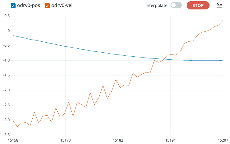
And here’s the Serial Plotter (Tools > Serial Plotter):
Troubleshooting
Arduino hangs at Waiting for ODrive...
This means the Arduino is not receiving heartbeat messages from the ODrive.
Make sure heartbeat messages are enabled according to Configuring the ODrive.
Make sure the configured CAN baudrate of the ODrive and the Arduino sketch match. The default for the Arduino sketch is 250000 while the ODrive uses automatic baudrate detection by default since firmware version 0.6.11. On earlier firmware versions, the ODrive default is also 250000.
Likewise, make sure the configured Node ID matches between ODrive and Arduino sketch. The default is 0 for both.
Double check your wiring.
In the example sketch, in the
onMessage()function, insert aSerial.println()statement. This can help you debug if your Arduino is receiving any CAN messages at all.If you have an oscilloscope, CAN logger or CAN-to-USB dongle, use them to check if there are any CAN messages on the bus.
Arduino hangs at Enabling closed loop control...
This means that the Arduino can talk to the ODrive and vice versa, but the ODrive refuses to enter closed loop control mode.
This can have lots of reasons (ODrive unpowered, ODrive not calibrated, etc.). The easiest way to find out why, is to open the GUI and check the status bar.
Arduino Library Reference
-
class ODriveCAN
Public Functions
-
bool clearErrors()
Clear all errors on the ODrive.
This function returns immediately and does not check if the ODrive received the CAN message.
-
bool setState(ODriveAxisState requested_state)
Tells the ODrive to change its axis state.
This function returns immediately and does not check if the ODrive received the CAN message.
-
bool setControllerMode(uint8_t control_mode, uint8_t input_mode)
Sets the control mode and input mode of the ODrive.
This function returns immediately and does not check if the ODrive received the CAN message.
-
bool setPosition(float position, float velocity_feedforward = 0.0f, float torque_feedforward = 0.0f)
Sends a position setpoint with optional velocity and torque feedforward.
This function returns immediately and does not check if the ODrive received the CAN message.
-
bool setVelocity(float velocity, float torque_feedforward = 0.0f)
Sends a velocity setpoint with optional torque feedforward.
This function returns immediately and does not check if the ODrive received the CAN message.
-
bool setTorque(float torque)
Sends a torque setpoint to the ODrive.
This function returns immediately and does not check if the ODrive received the CAN message.
-
bool setLimits(float velocity_limit, float current_soft_max)
Sets the velocity and current limits.
This function returns immediately and does not check if the ODrive received the CAN message.
-
bool setPosGain(float pos_gain)
Sets the position gain.
This function returns immediately and does not check if the ODrive received the CAN message.
-
bool setVelGains(float vel_gain, float vel_integrator_gain)
Sets the velocity and velocity integrator gains.
This function returns immediately and does not check if the ODrive received the CAN message.
-
bool setAbsolutePosition(float abs_pos)
Sets the encoder’s absolute position and enables absolute positioning.
This function returns immediately and does not check if the ODrive received the CAN message.
-
bool setTrapezoidalVelLimit(float vel_limit)
Sets the coast velocity for subsequent trapezoidal moves.
This function returns immediately and does not check if the ODrive received the CAN message.
-
bool setTrapezoidalAccelLimits(float accel_limit, float decel_limit)
Sets the acceleration and deceleration values for subsequent trapezoidal moves.
This function returns immediately and does not check if the ODrive received the CAN message.
-
bool getCurrents(Get_Iq_msg_t &msg, uint16_t timeout_ms = 10)
Requests motor current. Iq_measured represents torque-generating current.
This function will block and wait for up to timeout_ms (default 10msec) for ODrive to reply
-
bool getTemperature(Get_Temperature_msg_t &msg, uint16_t timeout_ms = 10)
Requests motor temperature.
This function will block and wait for up to timeout_ms (default 10msec) for ODrive to reply
-
bool getError(Get_Error_msg_t &msg, uint16_t timeout_ms = 10)
Requests error information.
This function will block and wait for up to timeout_ms (default 10msec) for ODrive to reply
-
bool getVersion(Get_Version_msg_t &msg, uint16_t timeout_ms = 10)
Requests hardware and firmware version information.
This function will block and wait for up to timeout_ms (default 10msec) for ODrive to reply
-
bool getFeedback(Get_Encoder_Estimates_msg_t &msg, uint16_t timeout_ms = 10)
Requests encoder feedback data.
This function will block and wait for up to timeout_ms (default 10msec) for ODrive to reply
-
bool getBusVI(Get_Bus_Voltage_Current_msg_t &msg, uint16_t timeout_ms = 10)
Requests ODrive DC bus voltage and current.
This function will block and wait for up to timeout_ms (default 10msec) for ODrive to reply May trigger onBusVI callback if it’s registered.
-
bool getPower(Get_Powers_msg_t &msg, uint16_t timeout_ms = 10)
Requests mechanical and electrical power data (used for spinout detection)
This function will block and wait for up to timeout_ms (default 10msec) for ODrive to reply
-
bool reset(ResetAction action = ResetAction::Reboot)
Resets the ODrive with the given action.
Valid actions:
Reboot (0)
Save (1)
Erase (2)
-
inline void onFeedback(void (*callback)(Get_Encoder_Estimates_msg_t &feedback, void *user_data), void *user_data = nullptr)
Registers a callback for ODrive feedback processing.
-
inline void onStatus(void (*callback)(Heartbeat_msg_t &feedback, void *user_data), void *user_data = nullptr)
Registers a callback for ODrive axis state feedback.
-
inline void onTorques(void (*callback)(Get_Torques_msg_t &feedback, void *user_data), void *user_data = nullptr)
Registers a callback for ODrive torques feedback processing.
-
inline void onTemperature(void (*callback)(Get_Temperature_msg_t &feedback, void *user_data), void *user_data = nullptr)
Registers a callback for ODrive temperature feedback.
-
inline void onBusVI(void (*callback)(Get_Bus_Voltage_Current_msg_t &feedback, void *user_data), void *user_data = nullptr)
Registers a callback for ODrive bus voltage/current feedback.
-
inline void onCurrents(void (*callback)(Get_Iq_msg_t &feedback, void *user_data), void *user_data = nullptr)
Registers a callback for ODrive currents feedback.
-
inline void onError(void (*callback)(Get_Error_msg_t &msg, void *user_data), void *user_data = nullptr)
Registers a callback for ODrive error messages.
-
void onReceive(uint32_t id, uint8_t length, const uint8_t *data)
Processes received CAN messages for the ODrive.
-
template<typename T>
inline bool request(T &msg, uint16_t timeout_ms = 10) Sends a request message and awaits a response.
Blocks until the response is received or the timeout is reached. Returns false if the ODrive does not respond within the specified timeout.
-
template<typename T>
inline T getEndpoint(uint16_t endpoint_id, uint16_t timeout_ms = 10) Get value at the endpoint.
Blocks until the response is received or the timeout is reached.
- Template Parameters:
T – The data type expected from the endpoint
- Parameters:
endpoint_id – Unique ID from flat_endpoints.json
timeout_ms – Time to wait for a response from ODrive
- Returns:
T Data from the endpoint, or 0 on timeout
-
template<typename T>
inline bool setEndpoint(uint16_t endpoint_id, T value) Set endpoint to value.
This function returns immediately and does not check if the ODrive received the CAN message.
- Template Parameters:
T – Type of the value from flat_endpoints.json
- Parameters:
endpoint_id – Unique ID of endpoint from flat_endpoints.json
value – value to write to the endpoint
-
bool clearErrors()